Fixing the Original Reverse Camera

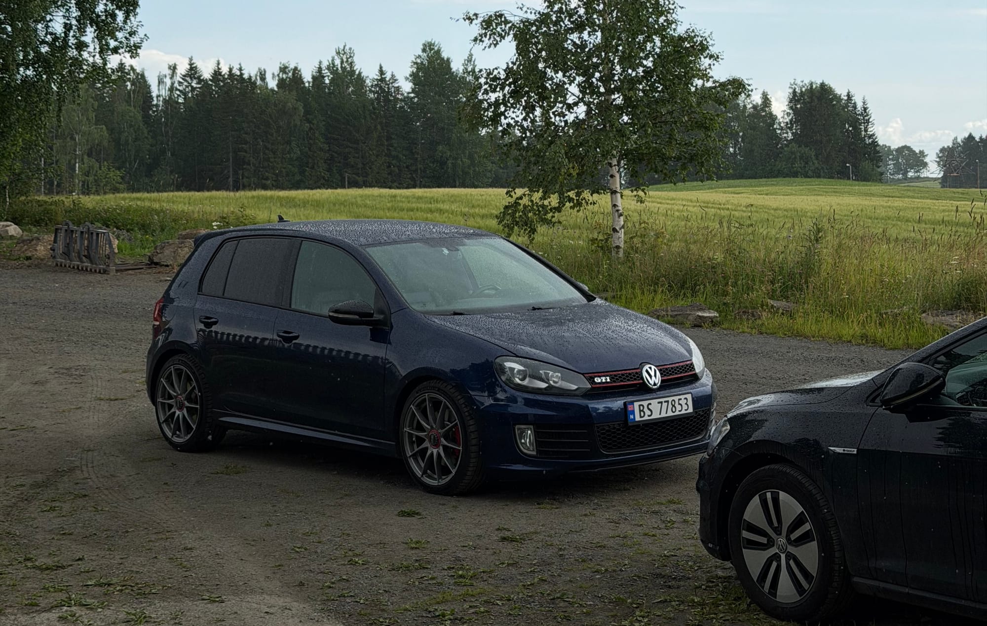
Last time, the Golf was finally running again.
Since then, it has been great. I have only really taken it on one proper joyride with some friends, and other than that I have continued driving it carefully. No strange noises from the engine, no smoke, and no new warning lights.
So naturally, I decided to start working on something electrical instead: The reverse camera.
Testing the aftermarket camera
I previously ordered a complete aftermarket flip-camera assembly for the Golf:

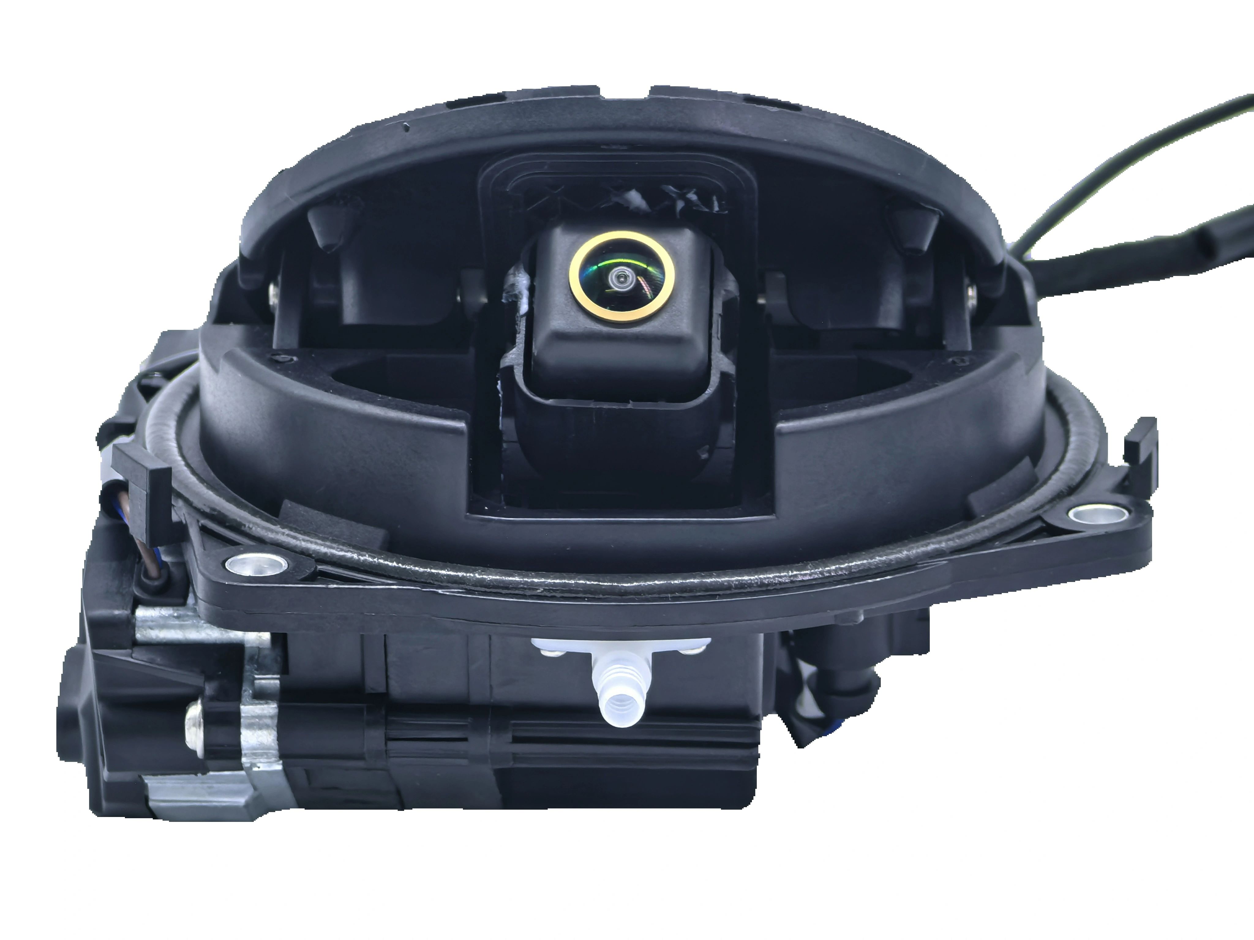
(I chose the dynamic one, non-AHD)
This replaces the entire rear emblem mechanism, including the motor and camera, and is designed to work with newer radios such as my RCD 880 Pro.
The original camera system was made for the RNS 510, while the RCD 880 Pro expects a normal composite video signal through an RCA connection. The aftermarket camera outputs CVBS, so in theory it should connect directly without needing an additional video converter.
Before permanently installing anything, I wanted to test it.
The supplied harness replaces the blue camera connector in the Quadlock with one that terminates in a female RCA socket. I connected the camera’s video cable to that, used a fuse tap to provide power, and found a suitable grounding point below the driver-side A-pillar.
For the reverse trigger, I temporarily pushed the blue trigger wire into the reverse-light connector. There was a small enough gap for it to make contact, which was good enough for testing. This was obviously not intended to be a permanent installation.
With half the interior hanging apart and wires running through the cabin, I turned on the ignition and selected reverse.
And there it was.
A working reverse camera on the RCD 880 Pro.
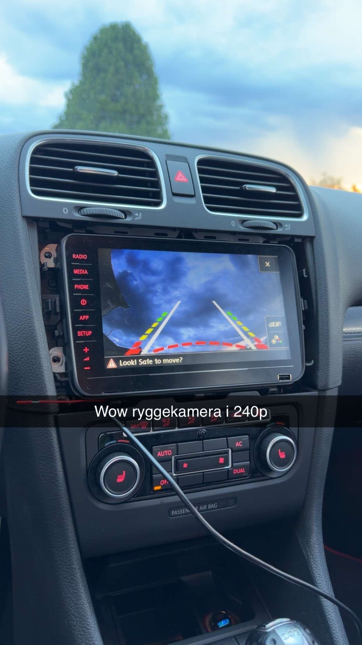
The image looked good, the field of view was much wider than the original camera, and there was no converter box involved. For a brief moment, this looked like it was going to be an easy retrofit.
It was not.
Cold diagnosis strikes again
The camera requires a 12-volt reverse signal to tell the emblem mechanism when to open. The obvious place to obtain that signal is the reverse light.
Unfortunately, the European Mk6 Golf performs cold-bulb diagnosis.
Even while the reverse light is switched off, the car briefly sends a small electrical pulse through the circuit to check whether the bulb is still connected. The pulse is too short to visibly illuminate a normal bulb, but the aftermarket camera’s electronics are sensitive enough to detect it.
That means every time I turn the key to the accessory or ignition position, the rear emblem opens and remains open for around 15 seconds.
It is not exactly subtle.
You can park the car, walk into a shop, come back, turn on the ignition, and then drive away with the rear camera still hanging open. It eventually closes, but not before making it look as though the car has become confused about which direction it is travelling.
So I started searching for a solution.
I looked through what felt like every forum post ever written about Mk6 reverse lights, bulb monitoring and aftermarket cameras. The usual recommendation was to disable cold diagnosis for the reverse light through coding.
On some Volkswagen models, this can apparently be changed individually.
On mine, it cannot.
I connected VCDS and checked the available adaptations in the Central Electronics module, but there was no channel for disabling the reverse-light cold diagnosis. There may be other BCM versions that expose the setting, but mine does not.
Because of course it does not.
Trying the original camera trigger
While looking at the factory reverse-camera wiring, I noticed that the original emblem assembly does not appear to take its trigger directly from the reverse-light connector. Instead, it has a separate four-pin connection in the boot.
That looked promising.
I measured the pins with a multimeter and identified the ground, permanent supply and what appeared to be the reverse trigger. From memory, pin 3 was the trigger wire, although anyone repeating this should verify the pins on their own car instead of blindly trusting that number.
When I selected reverse, the pin produced the expected signal and opened the aftermarket camera.
Perfect.
Except it also reacted when the ignition was switched on.
The dedicated factory connector may be physically separate from the reverse-light connector, but its trigger is evidently still derived from the same monitored reverse-light circuit. It carries the same diagnostic pulse.
So after finding the factory trigger wire, measuring it, testing it and briefly believing I had solved everything, I ended up exactly where I started.
Very productive.
Returning to the original camera
At that point, I went back to repairing the original RNS 510 camera.
In the previous post, I showed the damaged terminals and wires inside the original camera connector. The camera itself appeared to be usable, but the small internal harness had been cut and damaged badly enough that it could no longer be connected reliably.
After searching through far too many connector catalogues and comparing terminal shapes, I eventually found a replacement harness on AliExpress:

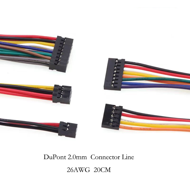
Double Row 2X4P, 20CM 26AWG
It comes as a pack of five harnesses, which is useful because it gives you several attempts if you damage a terminal while depinning it.
The original camera has two internal connectors. The blue connector appears to carry the video signal, while the black three-pin connector handles power, ground and the remaining camera connection.
In my case, the main damage was around the three-pin side and the wires leading between the two connectors.
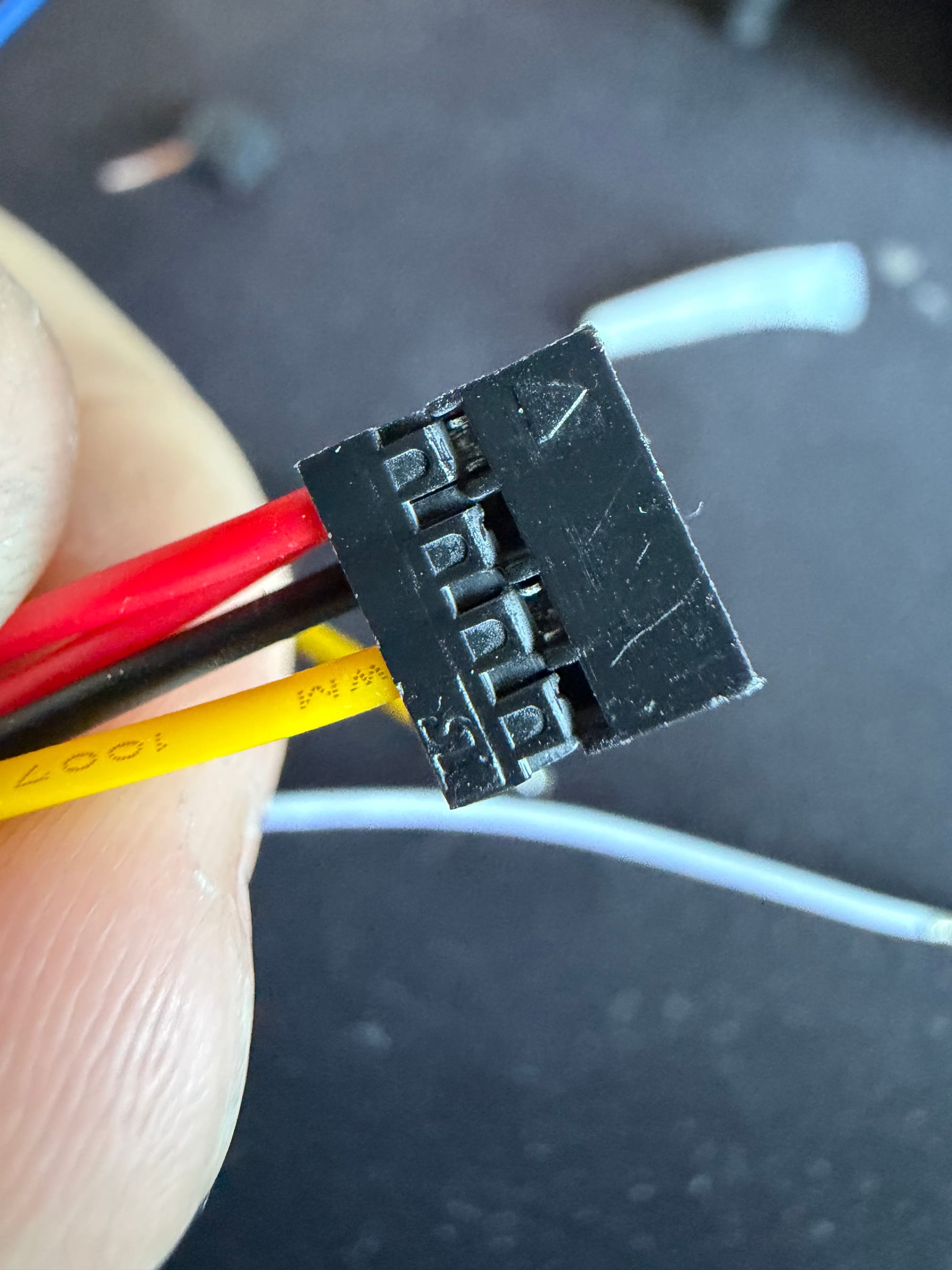
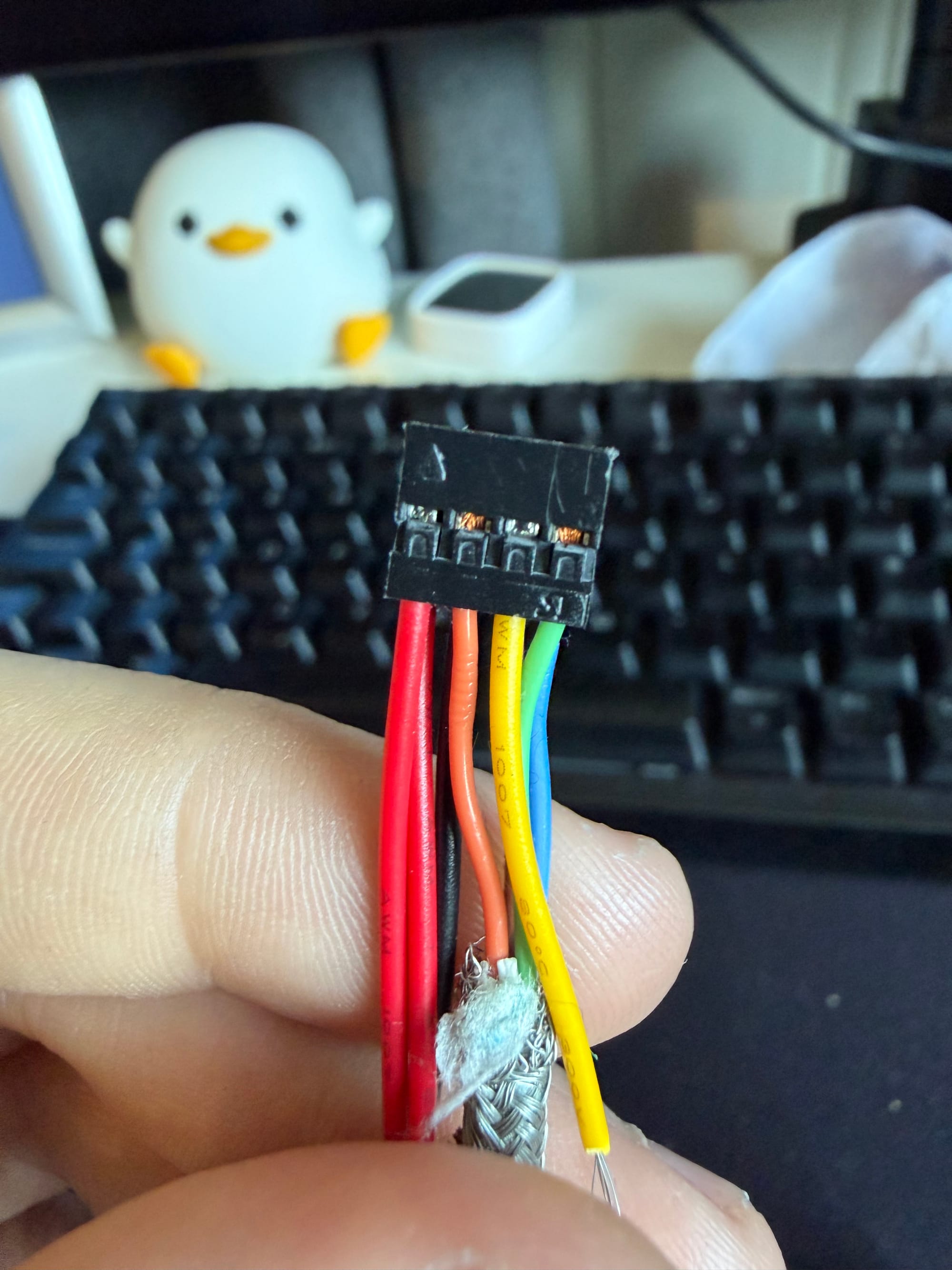
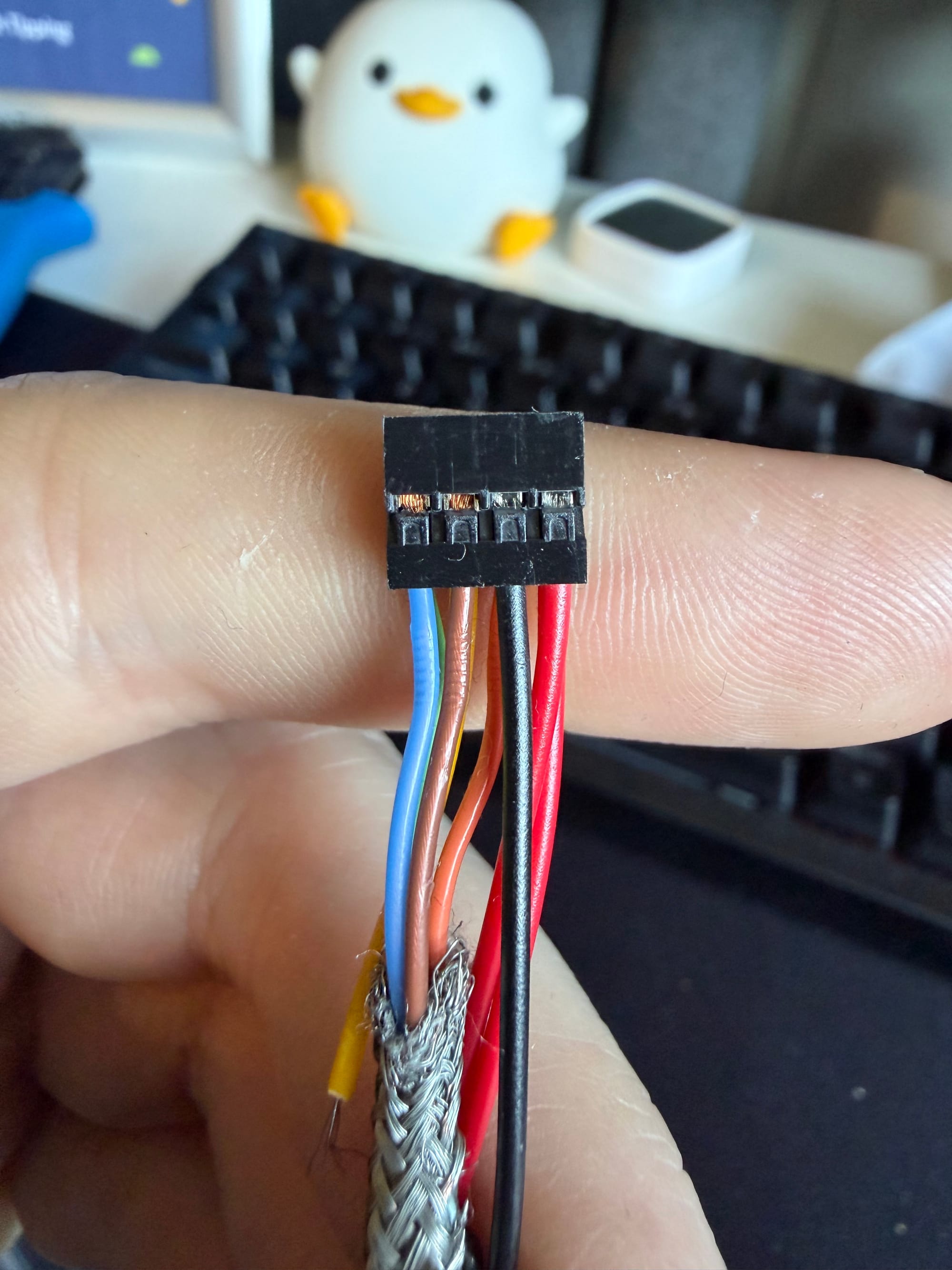
The replacement harness already had the correct blue connector and terminals, but the wires were arranged differently. I therefore removed the unnecessary terminals from the new connector, depinned the original blue video wires, and transferred them into the new housing.
That left me with a complete replacement connector and enough undamaged wire to splice it into the original camera harness.
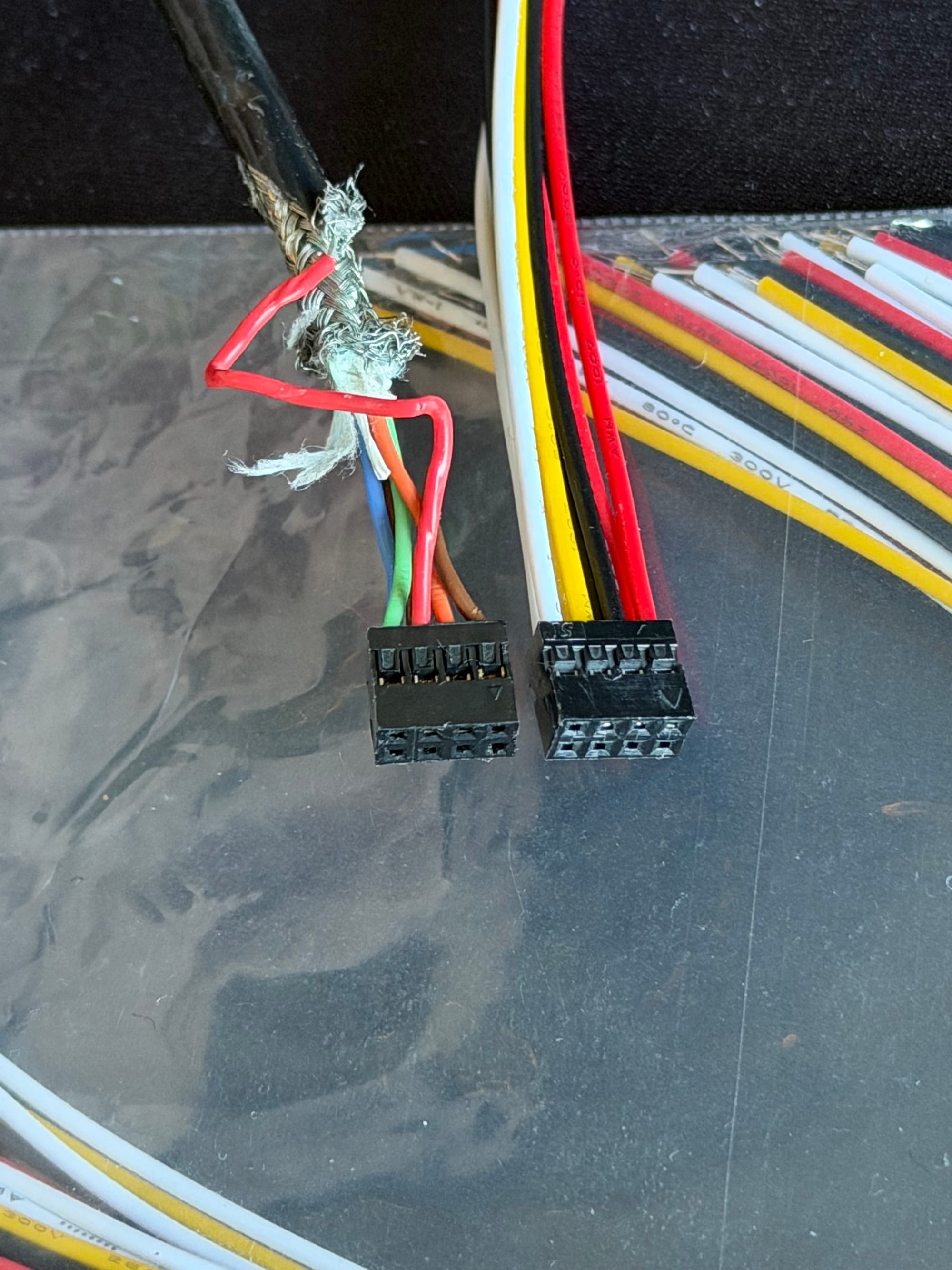
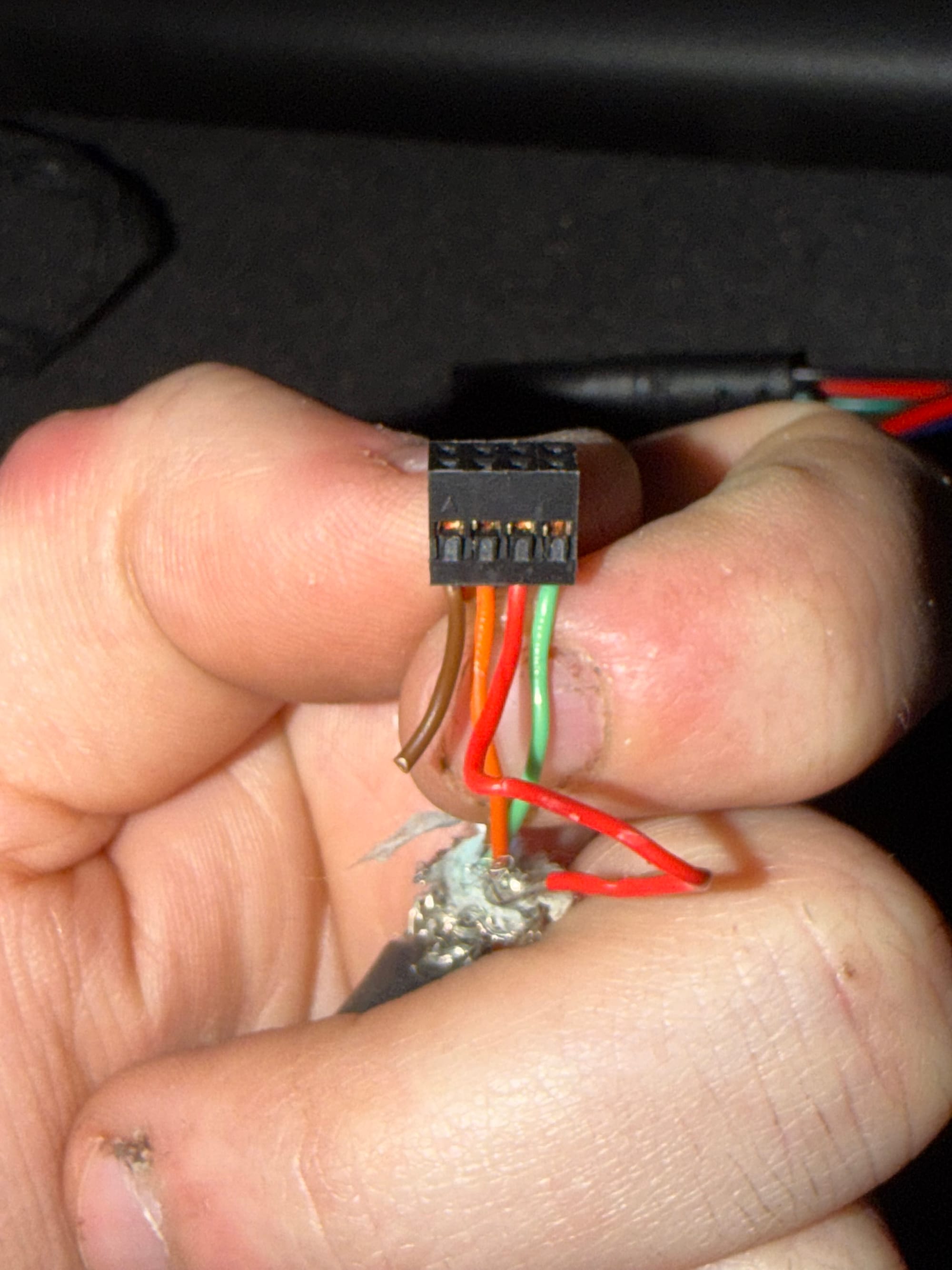
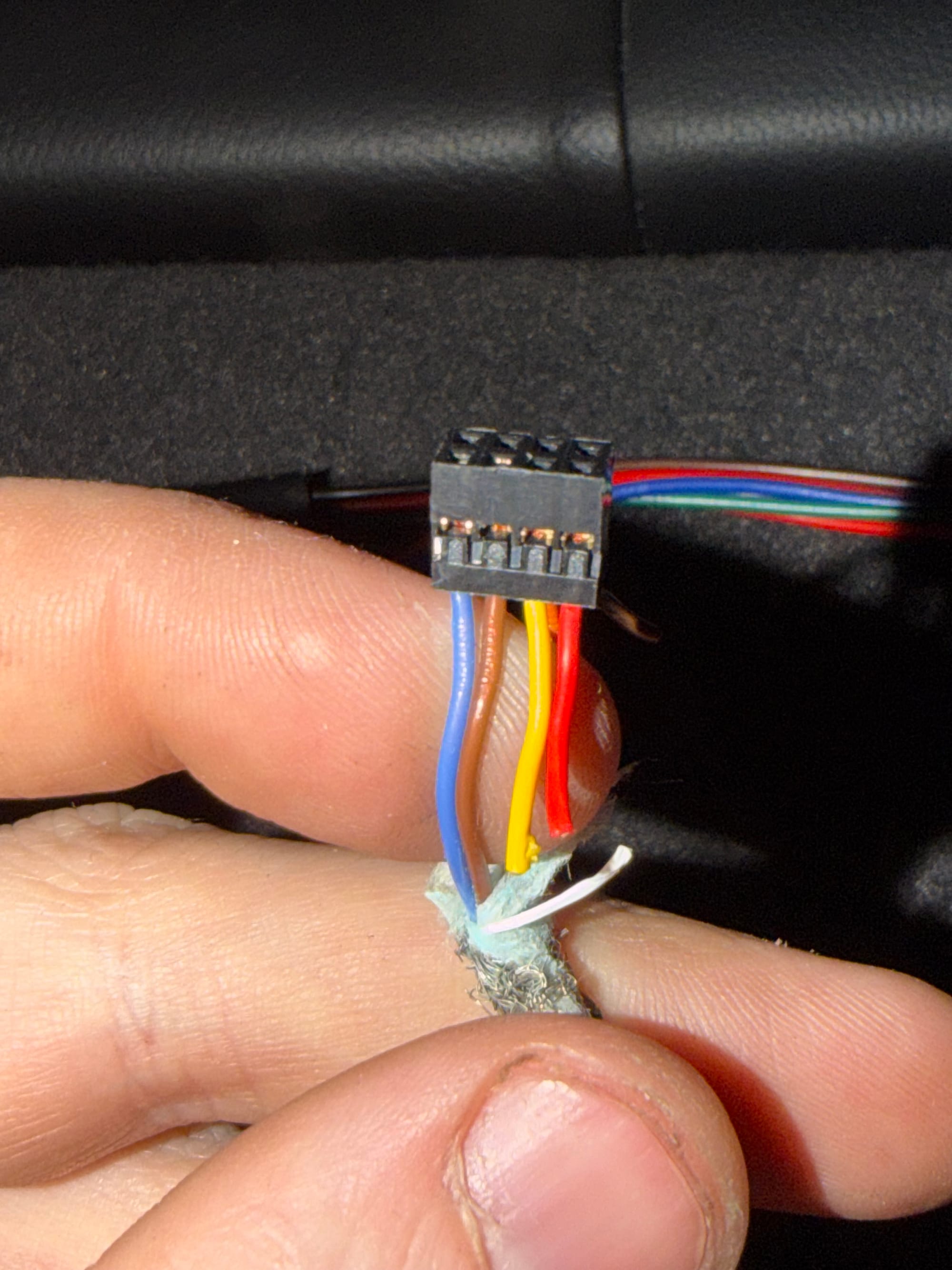
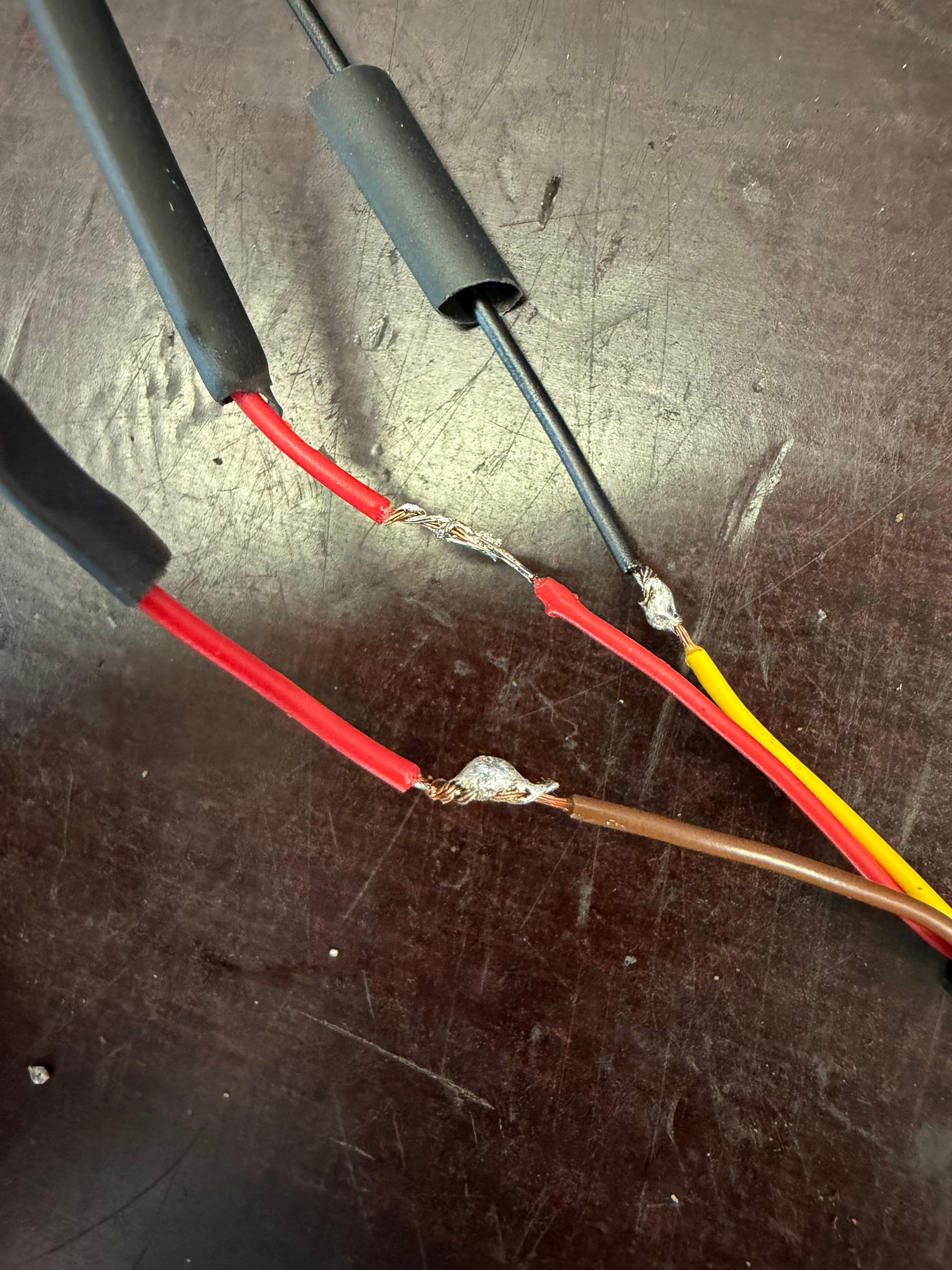
The original wiring, for anyone who needs it. The cut off wires (brown img-1, yellow and red img-2) go to the 3-pin connector
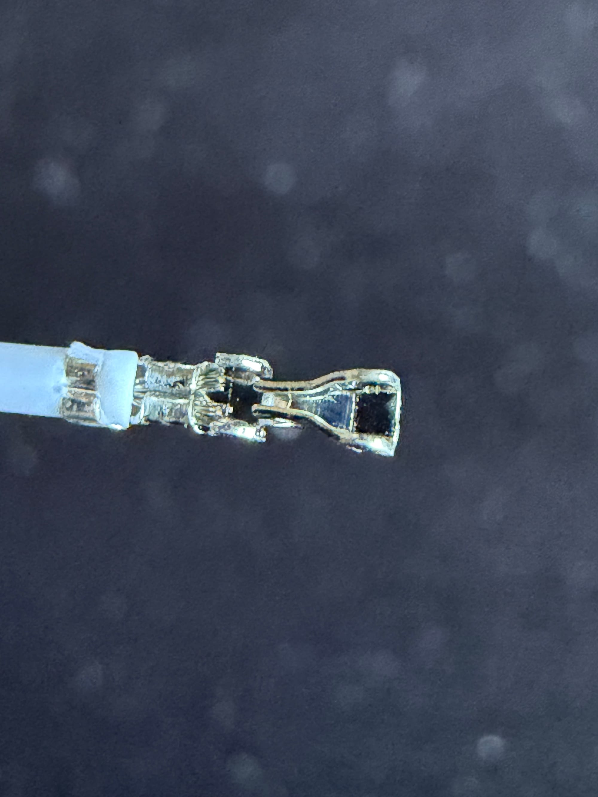
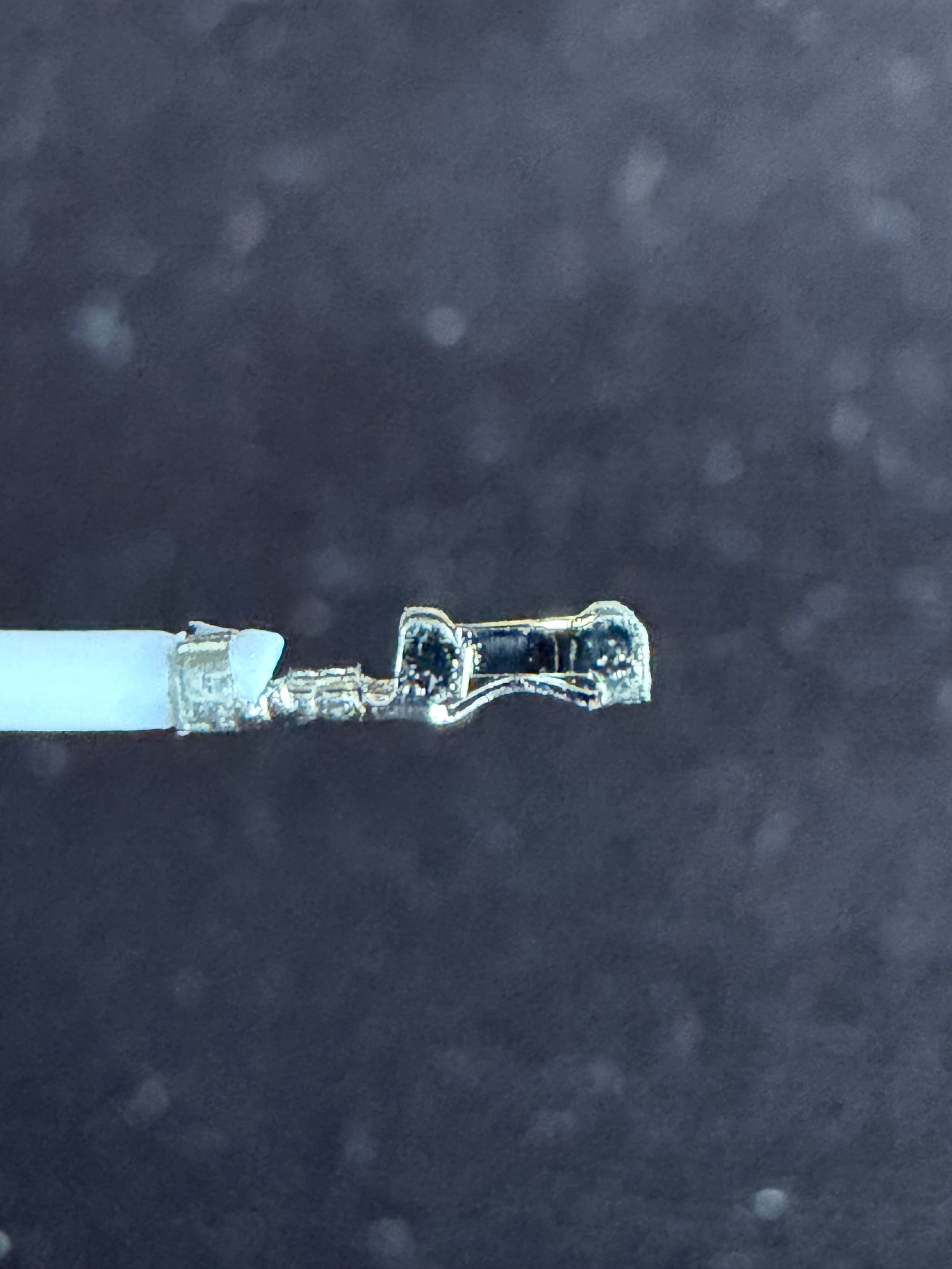
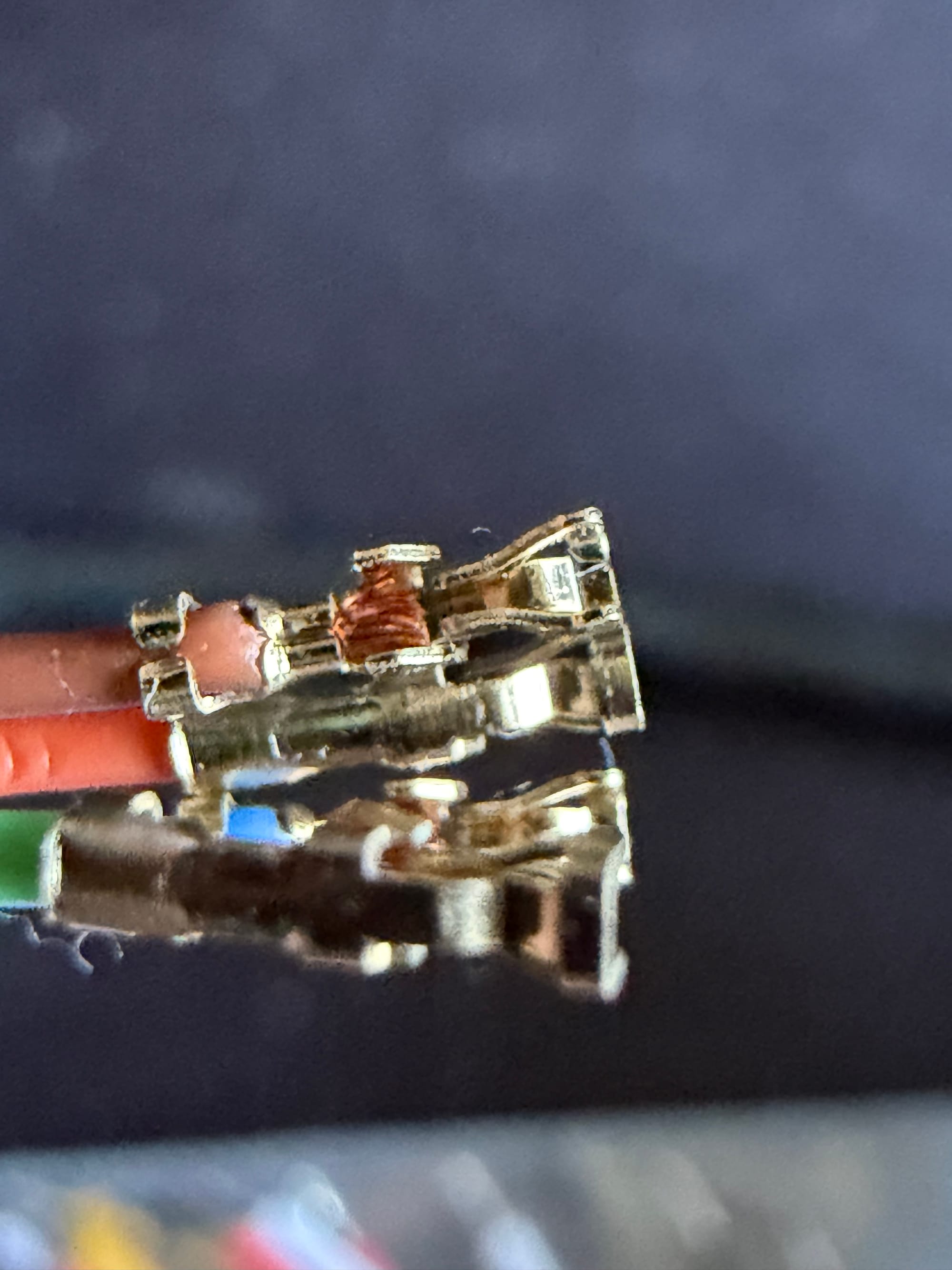
The new terminals vs the original
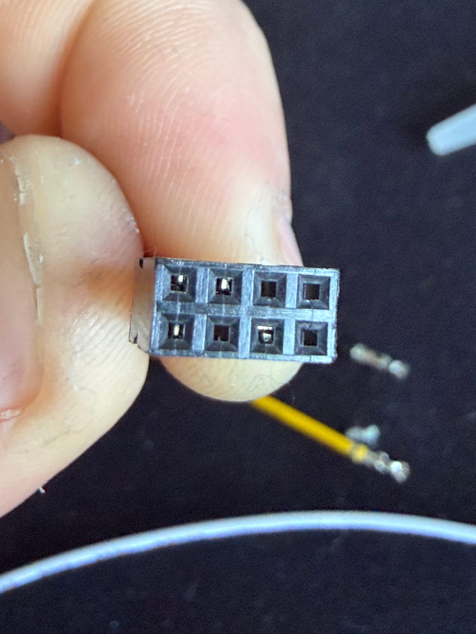
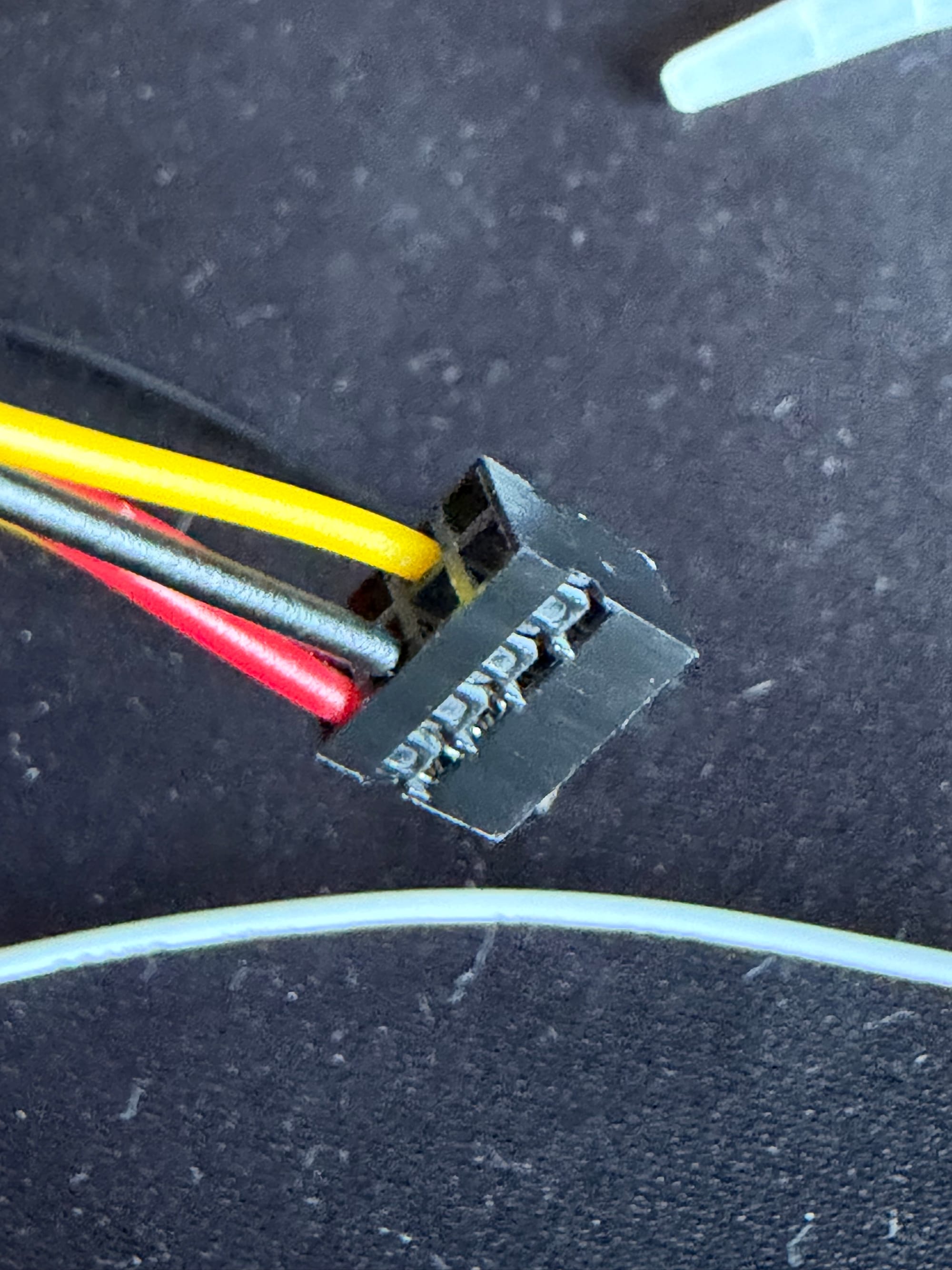
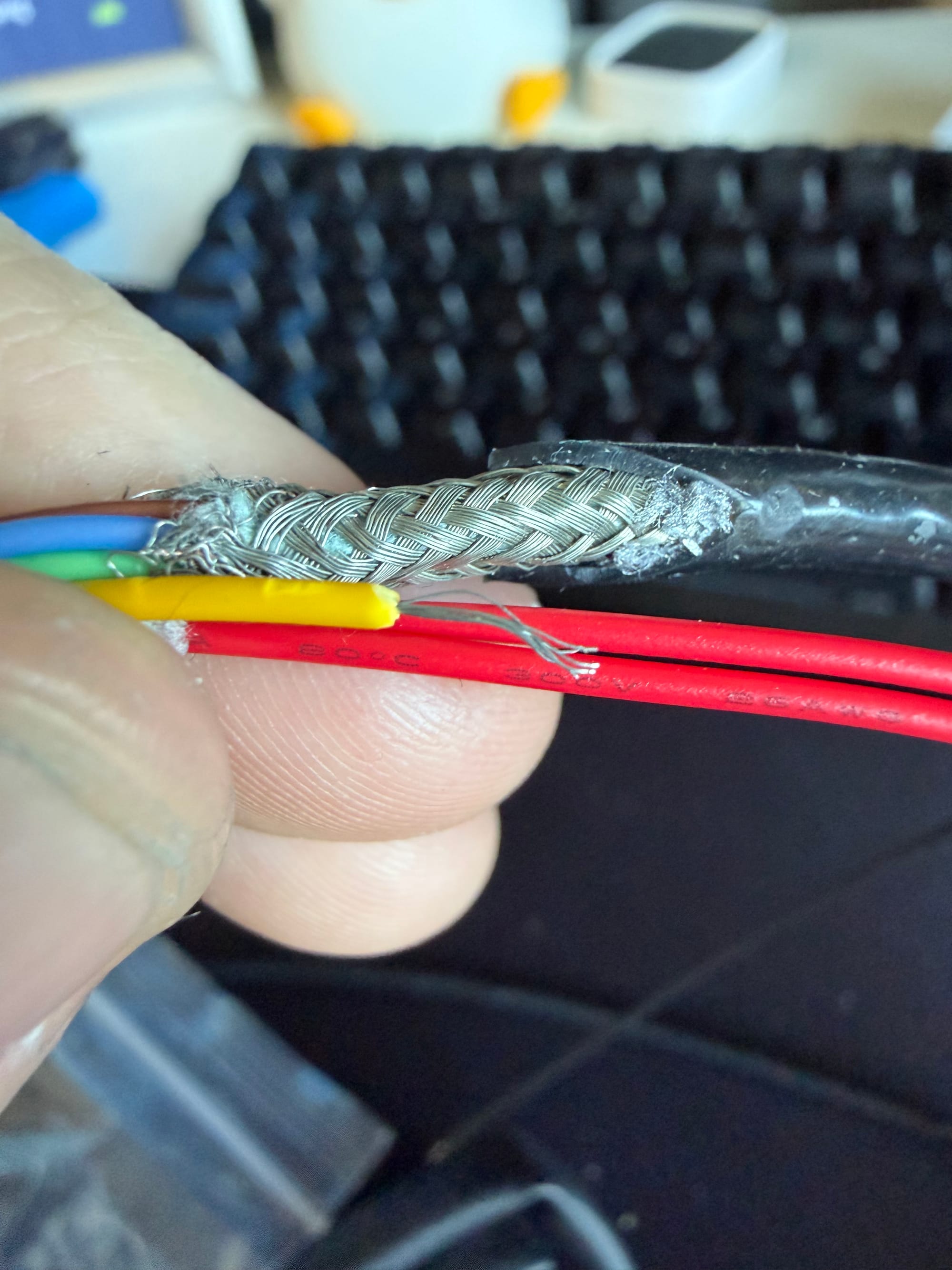
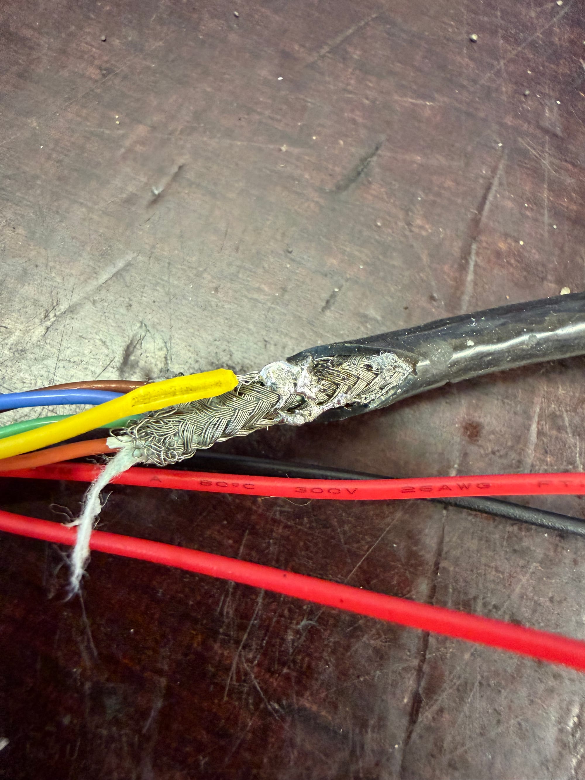
The video wiring is shielded. In addition to the insulated signal conductors, there is a bare drain wire connected to the metallic shielding around the cable. That shielding helps protect the video signal from electrical interference, so it needed to be reconnected rather than cut away and ignored.
I soldered the drain wire back to the cable shielding, followed by the remaining conductors for the three-pin connector.
Each soldered joint was insulated individually with small-diameter heat-shrink tubing. I then covered the repaired section of the video harness with a larger piece of heat-shrink tubing to support the wires and provide some strain relief.
That sounds far more professional than “I soldered everything together and covered it so none of the wires could touch,” but that is essentially what happened.
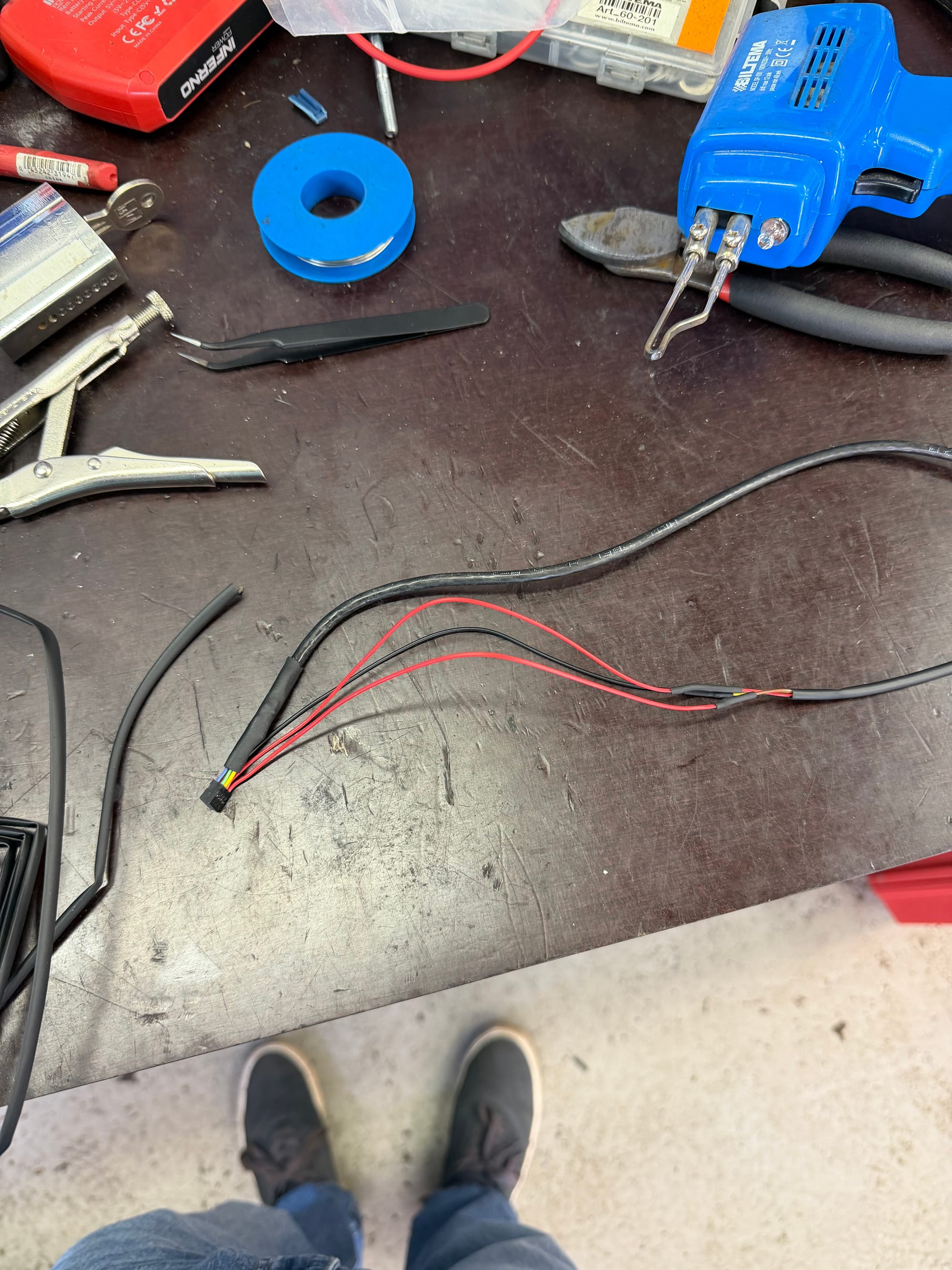
And just like that, the original camera had a complete internal wiring harness again.
Figuring out the connector orientation
There is one small problem with rebuilding this connector: its orientation inside the camera is not especially obvious.
The camera housing has a green reference mark in one corner. After searching for photos of the original camera using its OE part number, I found several images that showed the connector fitted with the green wire facing that mark.
There was no diagram explicitly confirming this, but the photos were consistent enough that I decided to trust them.
Or, more accurately, I gambled that Volkswagen had put the green mark there for a reason.
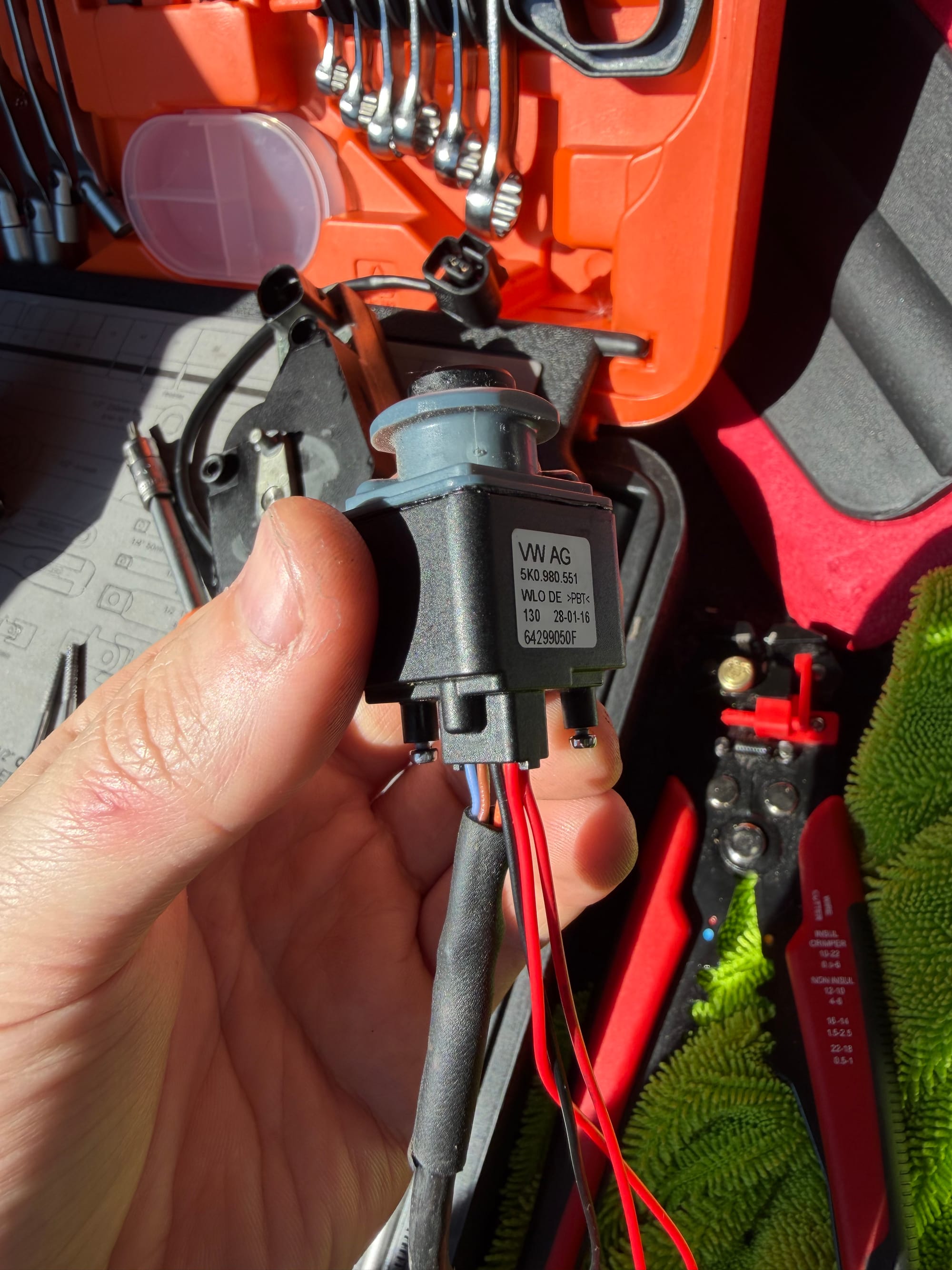
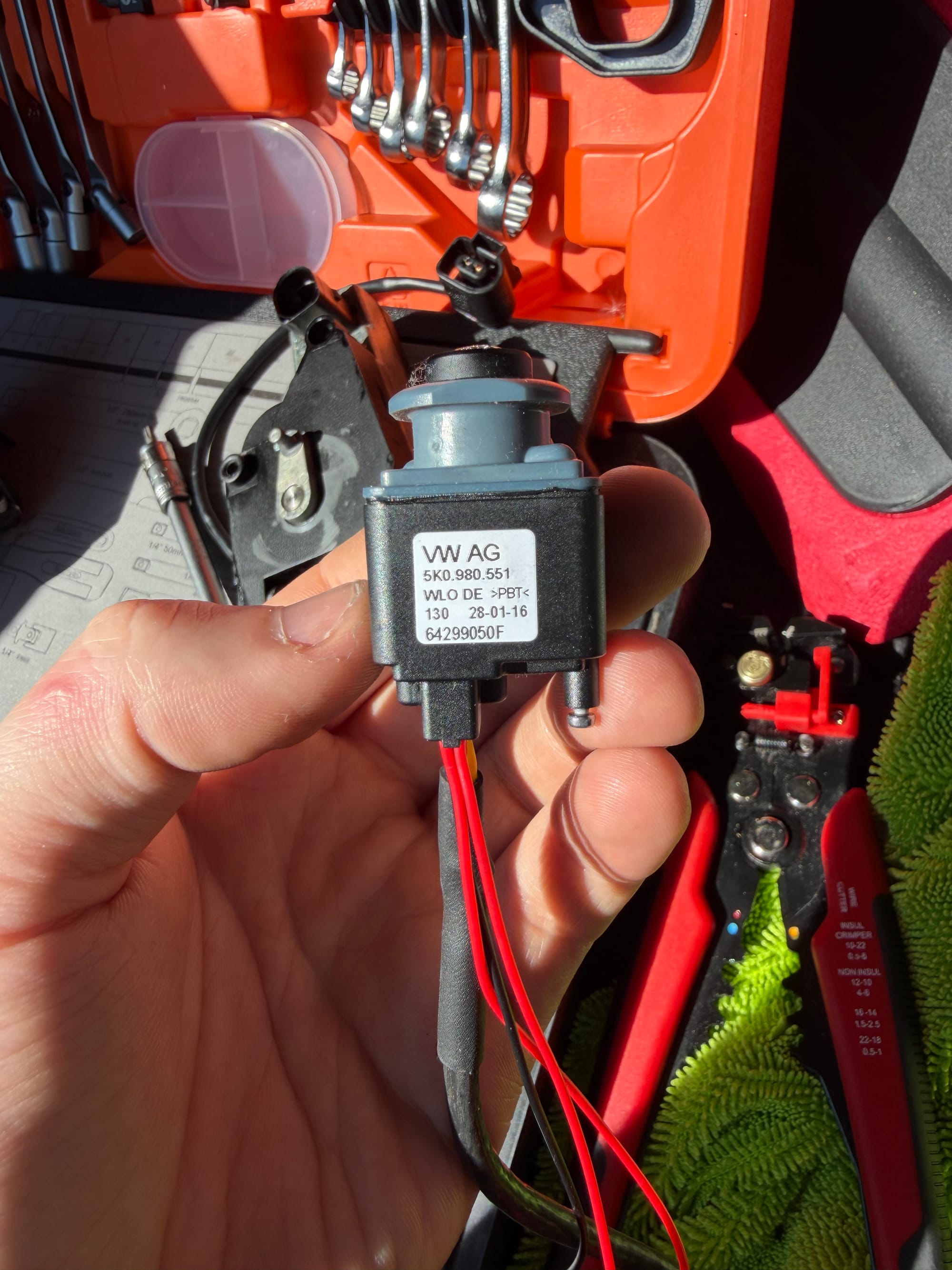
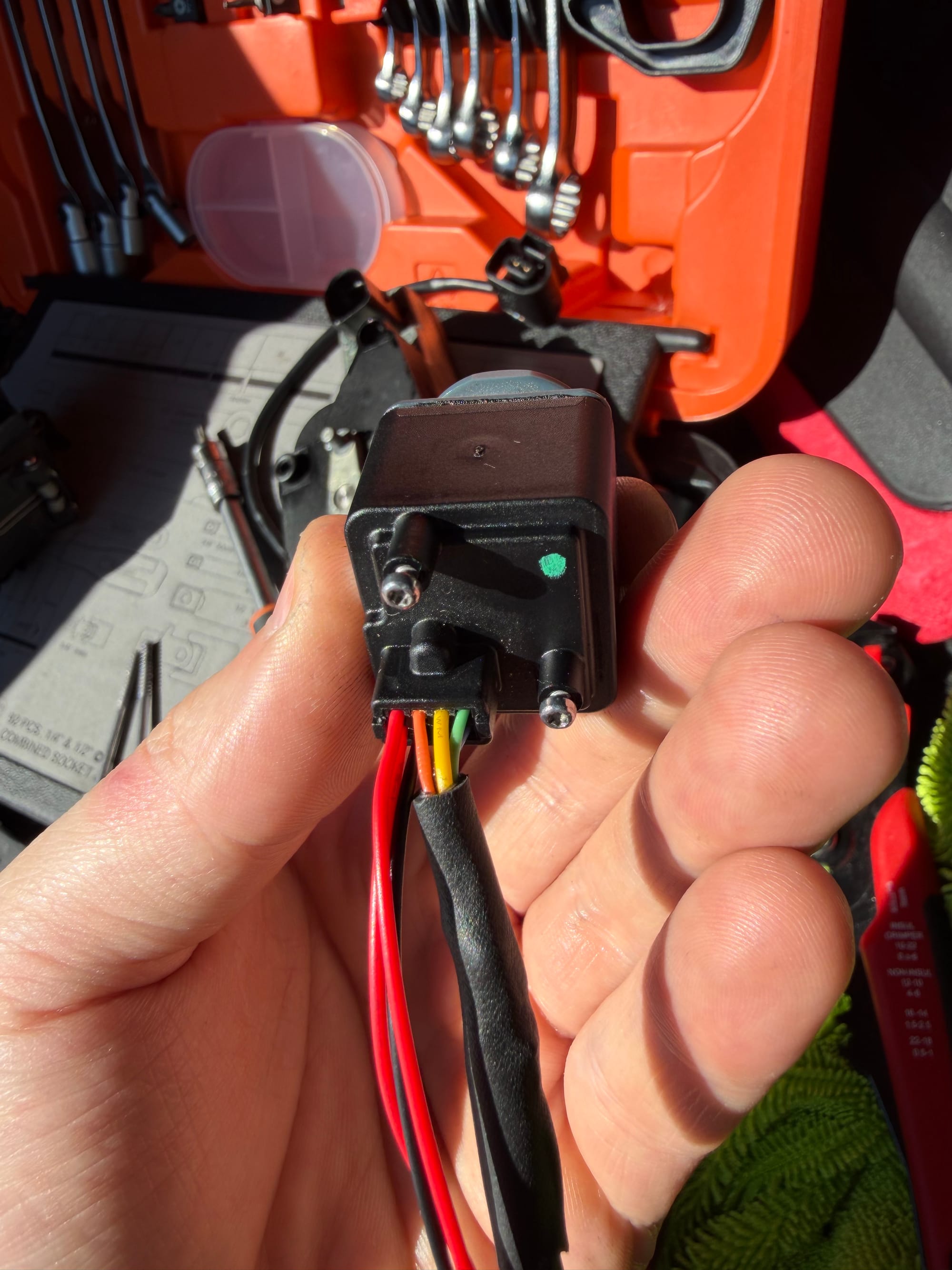
I connected the replacement harness in that orientation and prepared to test the camera.
This is where the order of events became slightly less intelligent.
Testing everything in the wrong order
Before fully rebuilding the emblem assembly, I connected the camera and wiring while leaving most of it hanging inside the boot. The camera motor is fairly heavy, so I did at least screw that part into the housing rather than letting its weight pull on the newly repaired wires.
I then turned on the radio, selected reverse and waited for an image.
Nothing happened.
I checked the camera wiring again. I checked the connector orientation. I checked that the emblem was opening. I started wondering whether the camera itself was dead after all.
Then I pulled the radio out.
The camera was not connected to it.
The original camera cable was still sitting behind the radio, completely disconnected, while I had been testing everything at the other end of the car.
Excellent diagnosis.
Once the radio was out, I also realised that I had a more fundamental compatibility problem. The factory RNS 510 camera does not output the standard CVBS signal expected by the RCD 880 Pro. The original system uses an RGB video connection, while the newer radio takes composite video through RCA.
That meant I could not properly test the repaired factory camera with the RCD 880 Pro, regardless of how well I had repaired its wiring.
This was when I decided to connect the complete aftermarket CVBS camera instead, which led to the successful test and the cold-diagnosis problem described earlier.
Eventually, I retrieved the original RNS 510 from storage and connected that instead.
With the original radio installed, the repaired camera worked.
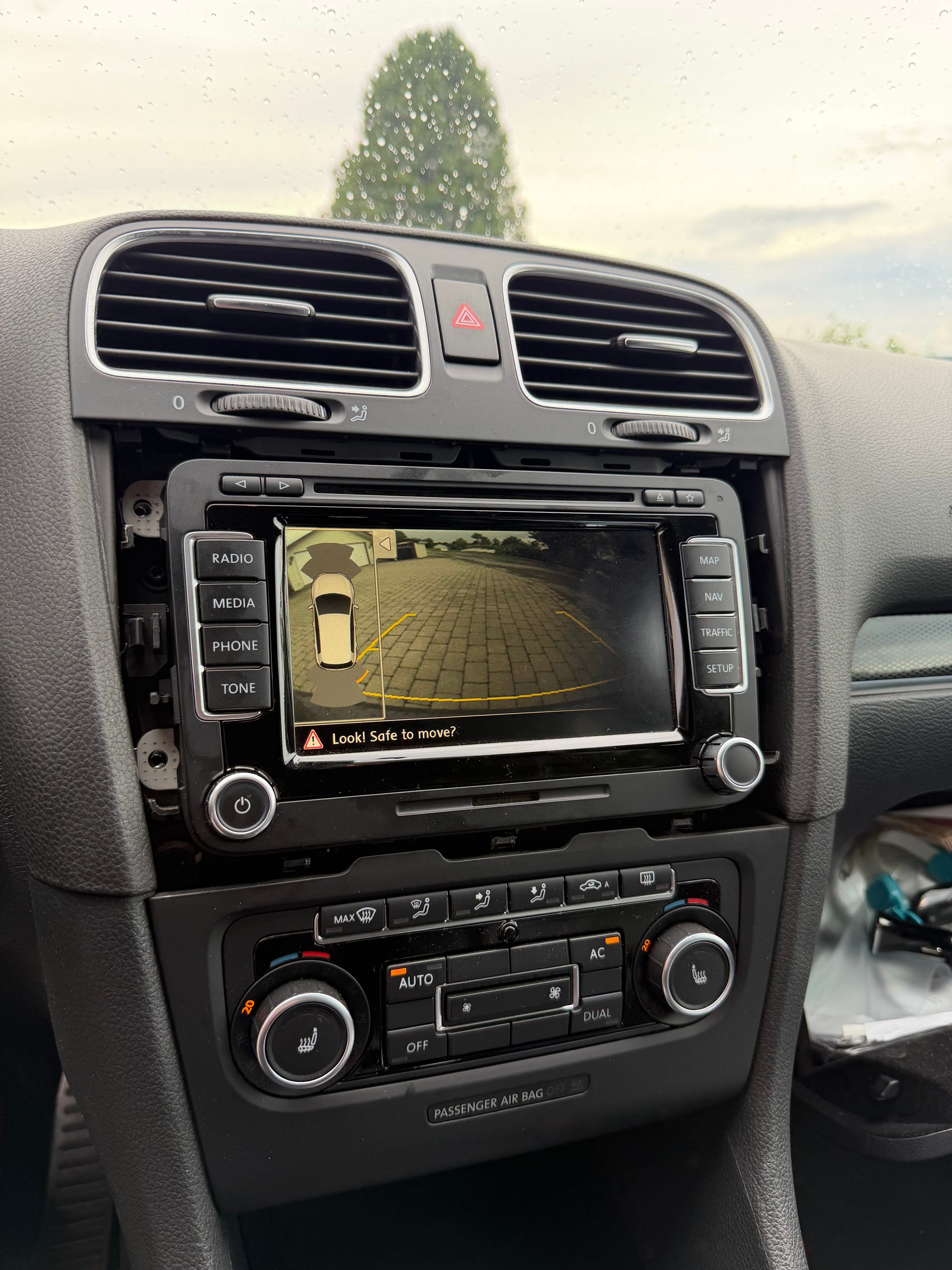
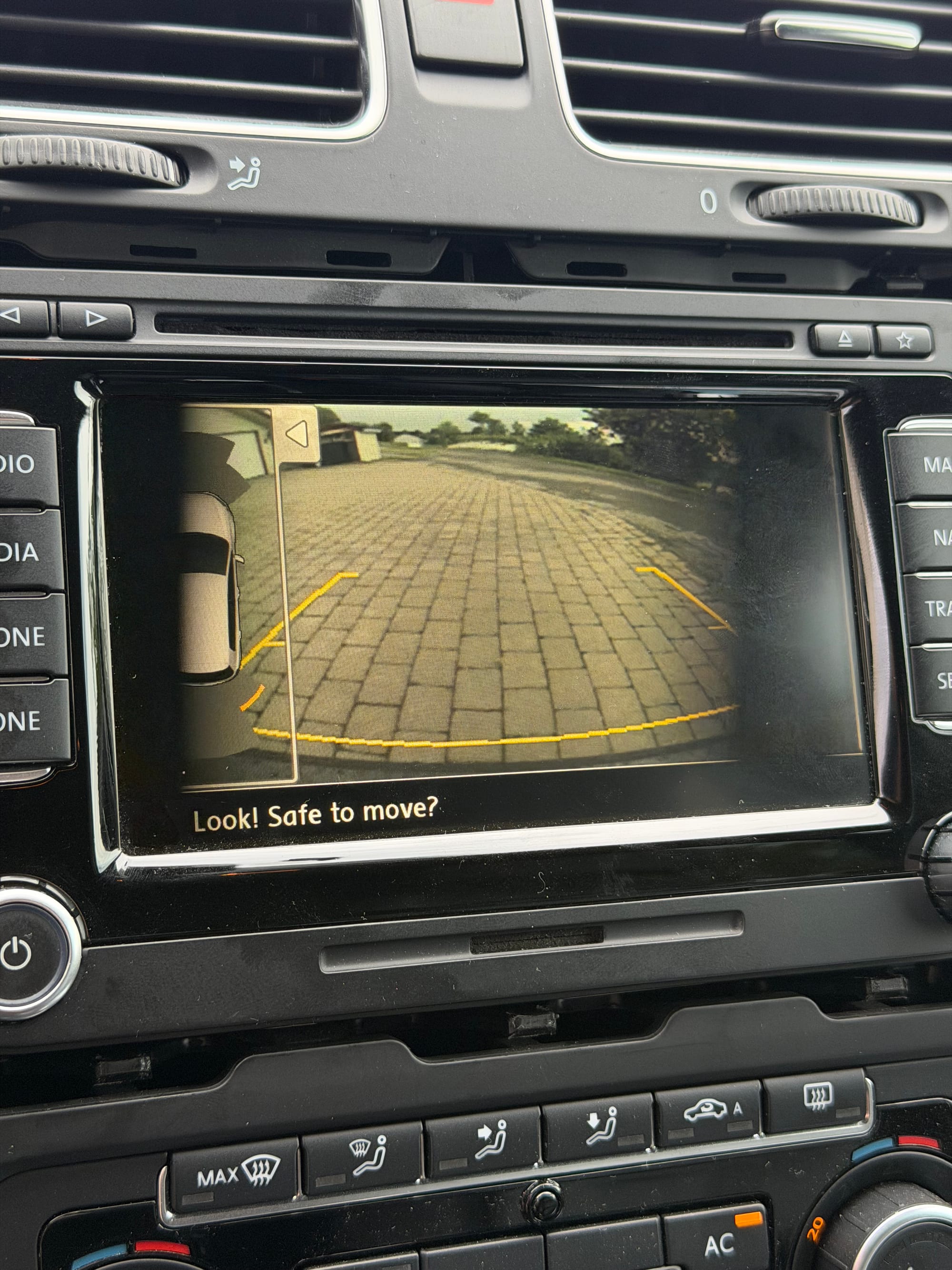
Camera angle makes the image look weird, ignore the black fading on the screen
So for anyone with an original Mk6 Golf flip camera that has damaged wiring inside the emblem, it is possible to repair it without replacing the entire camera assembly. At least in my case, replacing the connector housing, transferring the original video terminals and rebuilding the damaged wiring was enough to bring it back.
The only remaining problem is that it works with the radio I no longer particularly want to use.
Original camera or newer radio
For the moment, I have two working combinations.
The original RNS 510 works with the repaired original reverse camera. It opens correctly, does not react to the bulb-check pulse and integrates with the car exactly as Volkswagen intended.
The RCD 880 Pro works with the aftermarket CVBS camera. Its audio quality is noticeably clearer than the RNS 510, and the camera image has a wider field of view, but the emblem opens every time the car performs the reverse-light diagnosis.
Neither combination gives me everything I want.
The aftermarket camera was advertised as having a 170-degree field of view and a higher-resolution sensor. I have not found reliable specifications for the original camera, but its image is clearly narrower and less detailed.
However, CVBS itself is still a standard-definition analogue signal, so a camera advertised as “720p” does not necessarily mean the radio is receiving a true 720p image. The sensor may be capable of that resolution internally, but the composite output and the radio’s input will still determine what actually appears on the screen.
Either way, the newer camera looks better and shows considerably more of the area behind the car.
It just has the minor issue of opening whenever I turn the key.
Another possible solution
I have now ordered two replacement camera modules to test:

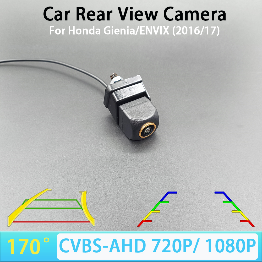
8421 CCD AHD720P, China Mainland, 12 V (720p 170deg)

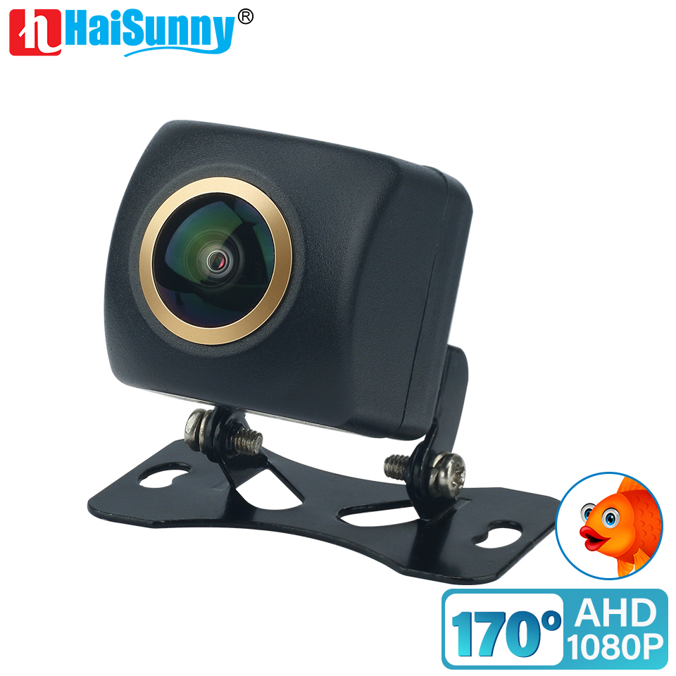
GAHD-B (1080p 125deg)
Unlike the complete aftermarket assembly, these are only the camera units. They are designed to fit inside an existing emblem housing and come with separate wiring for power and video.
I ordered two versions:
- 1080p with a 125-degree field of view
- 720p with a 170-degree field of view
Both are advertised with switchable AHD and CVBS output.
Again, the advertised sensor resolution does not necessarily mean the RCD 880 Pro will display that full resolution through CVBS. I also do not know the maximum analogue input resolution the radio can properly process.
That is what the testing is for.
The idea is to keep the original Volkswagen emblem assembly and motor, including the factory trigger that opens and closes it correctly, but replace only the original RGB camera module with one that outputs CVBS.
The factory emblem mechanism would continue behaving normally, while the replacement camera would send a compatible video signal to the RCD 880 Pro.
In theory, that gives me the best parts of both systems.
The new camera has its own power and ground connections, so it should not require replacing the entire wiring harness through the boot. I will need to find a suitable power source and run the composite video cable to the radio.
I would prefer to power it from an accessory-switched supply so it only receives power while the car is on. Constant power would probably work, but leaving an aftermarket camera permanently powered is not my first choice.
There is also the boot’s 12-volt outlet circuit, depending on how that is switched, or I can run a proper accessory supply from the fuse box. I will measure everything before deciding rather than assuming a wire behaves the way I want it to.
Before installing either camera into the emblem, I will test both of them in the cabin. I can connect them directly to the radio, compare the image quality and field of view, and confirm which output setting the RCD 880 Pro accepts.
Then I can decide whether the wider 170-degree view is worth the lower advertised resolution, or whether the narrower 1080p version produces a noticeably cleaner image.
That is the plan, anyway.
Plans involving this car have always been extremely reliable.
Getting slightly better at this
The positive side of all this is that my electrical skills are improving.
A while ago, finding an unfamiliar connector with four wires would have meant guessing, searching online and hoping somebody had already documented it. Now I am becoming more comfortable using a multimeter, checking continuity, identifying supplies and grounds, depinning connectors, rebuilding shielded wiring and testing things without immediately destroying them.
I am not going to claim I am suddenly an automotive electrician, but I now feel reasonably confident that I can deal with most of the smaller electrical problems this car throws at me.
Which is useful, because it seems determined to keep providing practice.
Once the camera situation is resolved, the next area I want to understand better is the suspension and subframe.
There is an occasional knock when the load on the car changes. I normally only hear it in one very specific situation: arriving home, turning the steering wheel almost fully, reversing down a slight slope and then reaching flat ground.
It is rare enough that I am not convinced it is a serious issue, but it sounds like something in the subframe or suspension shifts slightly as the load changes.
That could be a mount, a bushing, the subframe itself or something completely unrelated.
For now, the car drives well, the engine is healthy, the original reverse camera works again, and I have several new camera experiments on the way.
So overall, progress.
Just not in a particularly straight line.